
Tissue Mimicking Phantoms, Visual Acuity, and Dead Elements
G. Wayne Moore, B.Sc., MBA, FASE
06/09/20
Tissue mimicking phantoms (TMPs) have been used for ultrasound system performance testing and quality assurance validation since the early 1980’s. Prior to the 1980’s many ultrasound systems produced images that were bi-stable in B-mode with little or no gray scale gradations. Additionally, prior to the development of digital scan converters (DSCs), ultrasound systems employed analog scan converters that often had an annoying performance drift over time that would cause, among other issues, round targets to appear egg-shaped and distance measurements to be inaccurate. The primary use of pre-TMP ultrasound phantoms early on was to provide a mechanism for the service engineer to re-calibrate the ultrasound system so that round shapes became round again, and distance measurements become accurate. With the advent of DSCs electronic drift issues like those mentioned above became a thing of the past. DSCs also ushered in the age of modern gray scale imaging. At that time phantom manufacturers also began producing TMPs as a means of evaluating certain acoustic performance parameters associated with expanded gray scale ultrasound systems. It has been almost 35 years since TMPs were introduced and they are still basically the same device now as they were then. Ultrasound systems and probes as well as new imaging and Doppler modalities have not stood still. In fact, systems in 2017 are orders of magnitude more complex than their counterparts of 35 years ago. Yet many facilities still rely on TMPs as their primary tool for testing ultrasound probe and system performance. I wanted to focus this month’s article on why reliance on visual acuity to determine subtle variances in the B-mode image is insufficient.
Digital scan converters in an ultrasound system can only handle discrete numbers which have a limited number of places beyond the decimal point. Analog numbers coming into the system which fall between those values must be rounded up or down to the nearest available digital number so the scan converter can store it. The range of allowed values is determined by the bit-depth (word length) of the analog-to-digital scan converter. For example, a 6-bit (word length six bits long) scan converter will have a gray scale range of 26 or 64 levels of gray while an 8-bit scan converter will have a range of 28 or 256 levels of gray. From a display standpoint that means that the signal intensity of the returning echoes will drive a pixel on the monitor to one of 64, or 256 levels of gray depending on the scan converter’s bit-depth. The ratio of the largest to the smallest echoes detected and processed by the ultrasound system is known as the dynamic range of the device expressed in dB. In contemporary ultrasound devices 100dB and more is often expressed. The problem in displaying the full range of these echoes is that the bit-depths required to visualize the full dynamic range of the device are beyond the acuity of the human eye, which can only discern approximately 25, or 32 levels of discrete gray. The resulting processed ultrasound images shown on the system monitor are usually compressed to ~ 20dB. The two gray scale images below demonstrate the range of the human eye. The first is a gray scale test pattern from a GE L9 ultrasound system showing 15 levels of gray, the second image is 256 levels of gray. While it is easy to discern the 15 discrete levels in the GE image it is impossible for the human eye to distinguish 256 discrete levels of gray, it all tends to blur contiguously from one level of gray to the next to the next. The pacing issue in the ability of any given human to discern a given range of gray scale levels is their specific visual acuity. This is an important factor to consider when judging the performance of the system/transducer by simply looking at an image on the display monitor to spot subtle, or not so subtle deficiencies.

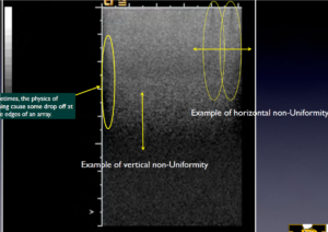
With basic B-mode imaging (shown below) two parameters of performance can be qualitatively assessed using a TMP; sensitivity (the ability to discern faint echoes) and uniformity (homogeneity of the echoes, see photo below, left). In addition to be a qualitative test this is also a subjective test as it relies on the visual acuity of the tester to detect small variances in the image. Using a TMP also is complicated by the desire (sometimes subconsciously) to make an image captured during today’s test “look” like the one that was captured during a previous test, usually by adjusting the TGC controls, gain, and various processing functions. Modern systems also have heavily averaged image processing algorithms such as Spatial Compounding that can mask transducer problems such as dead elements, as demonstrated in the image below, right. Lastly, because of the rather narrow range of gray scale visual acuity in humans the TMP test results can be misinterpreted by someone who may not be able to discern subtle differences in the image.
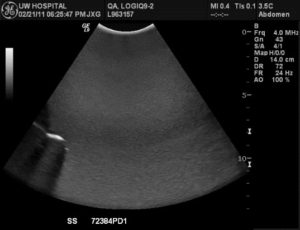
Spatial compounding masks subtle probe failures in this image with multiple dead elements in the array
CONCLUSION
Below is an abstract that was subsequently accepted for publication and presentation at the AAPM (American Association of Physicists in Medicine) meeting in June of 2005 by Dr. James Zagzebski, et al, regarding the limitations of TMPs in spotting subtle image degradation. See comment highlighted in red below. The fact is that although TMPs have a 35-year legacy as a test tool for B-mode ultrasound they have been for some time inadequate for evaluating the performance of modern ultrasound systems and probes. Ultrasound probes now contain sophisticated electronics within the scanhead housing and have element counts in excess of 9,000. Further, the ultrasound system has complex beamformer and other front-end electronics, as well as sophisticated image processing algorithms that can mask subtle changes in performance that can be early warnings of system or probe failure. There was a day when an image expert could “eye-ball” an ultrasound image and know what was wrong; but those days are gone.
Abstract – First published: June 2005, James Zagzebski, PhD, et all
Purpose: Ultrasound transducer performance plays a major role in the integrity of B-mode mages and in image quality. A frequent problem with arrays is “element drop out,” caused by electronic or mechanical interruption of signals. Currently this is detected using visual inspection of images of patients and or phantoms. Our objectives were to evaluate an electronic probe tester for determining functionality of array transducers and to compare results of the tester with subjective analysis of images of uniform phantoms. Method and Materials: A FirstCall 2000 (Sonora Medical Systems) electronic transducer tester was used on array transducers. The device exercises each element in the array, measuring its capacitance, pulse-echo sensitivity, pulse width, center frequency and bandwidth using planar targets. Probe adapters and software enable the FirstCall to utilize connection configurations of different transducer manufacturers. Probes from Siemens Sequoia and Philips HDI 5000 machines available in the UW Hospital were tested. Images of a uniform phantom were obtained from each transducer using sensitivity and gain settings for uniform gray scale. The images were examined for evidence of element dropout. Results: Of twenty-one probes initially tested, nine exhibited some level of malfunction (>2 “dead” elements). Of the nine, four exhibited a significant level of malfunction (>5 dead elements). Probes that had only a few dead elements showed no signs of image degradation in the phantom tests. When multiple (∼5 or more) elements are dead, manifestations of the problem appeared in the phantom images. Conclusion: The FirstCall provides an objective test of transducer performance, with greater sensitivity than a phantom test. The penalty for using a probe with only a few dead elements may seem minimal if no indication is seen in a uniform phantom image.
About the Author, G. Wayne Moore:
A 30-year veteran of the diagnostic ultrasound market Wayne has held senior level positions with several major medical equipment manufacturers, including Honeywell Medical Systems and Siemens Medical Solutions. Wayne has been directly involved in the development and commercialization of more than 15 technologically intensive ultrasound systems. He is widely published in diagnostic ultrasound literature, a sought after speaker at medical imaging conferences, has served as an expert witness in multiple ultrasound litigations, and holds more than 16 United States ultrasound related patents. Wayne obtained his MBA from the University of Denver – Daniels College of Business.
He was elected as a Fellow of the American Society of Echocardiography (FASE) in 2009.
Acertara Labs
Correspondence: Dave Dallaire
1950 Lefthand Creek Lane , Longmont, CO 80501, USA
Email: [email protected]
www.acertaralabs.com